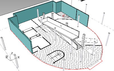
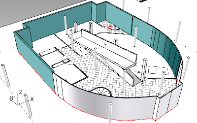
Ground floor walls
There are three ways to create walls in VisualARQ: vaWall. Drawing walls as if they were polylines.
 Wall: From curve. Turning curves into walls.
 Wall From Solid: Turning Rhino polysurfaces into VisualARQ walls.
Exterior and interior walls:

Straight walls
- Turn the layer with the Ground floor bitmap on.
- Run the _vaWall command
 to start drawing the walls as if you were drawing polylines. The wall insert dialog box will appear with the list of existing styles.
 - Wall insertion options: select the style, height or a specific alignment while you are drawing the walls, following the floor plan bitmap. You can change these wall insertion options for each piece of wall without closing the command.
Curved walls
- Use the Wall: From Curves command
 for the curved walls of the floor plan.
- Select the Curve used to create the inner Ground floor slab and Explode it with the _Explode command
 (you could also use the _Split command
  to split the curve from the point where the curved walls start).
 - Run the _vaWallFromCurves command
 (available in the Wall command toolbar). The wall insert dialog will appear.
 - Select the wall insertion options.
- Select the curve or multiple curves you want to turn into walls.
- Select the Curve used to create the inner Ground floor slab and Explode it with the _Explode command
- Change wall parameters: After the walls are created you can change their parameters (in the VisualARQ Properties in the Rhino Properties dialog box
 ).
). - Split a wall: Run the _vaWallSplit command
 to split a wall into two different walls:
- Select the wall you wish to split.
- point where you wish to split the wall. This point is always placed along the base line of the wall.
- Place the curved glass walls on the Glass layer.
Create and edit new wall styles

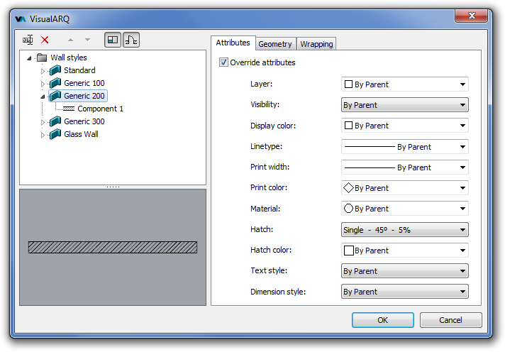
- Open the wall styles dialog: you can open it with the _vaWallStyles command by right-clicking on the wall icon, in the objects toolbar, or from the drop-down menu: Wall > Wall Styles.
- Create a new style: Press the New Style… button and follow the steps of the wall style wizard to define the new style parameters:
- Name
- Number of components
- Name and thickness of each component
- Wall Height (this is just a value by style, you can later change it by object)
- Wall reinforcements
- Edit the wall style: The new wall style appears in the list of wall styles. You can edit its parameters anytime by selecting the wall name or its components name: expand the wall style to see the components. Edit them from the Geometry and Reinforcements tab.
- Wall Attributes: You can assign the wall attributes, such as the layer they belong to, render material, or the hatch pattern, in the Attributes tab.
- Duplicate wall styles: To create new wall styles you can either repeat the steps through the “New wall style” wizard or just duplicate an existing wall style and edit its parameters later on. You can even add new components to a wall style by right-clicking on the style name (a context menu will be displayed) > New > Wall component.
Back to Index menu
