VisualARQ FEATURES
Project Management Tools
Buildings and Levels
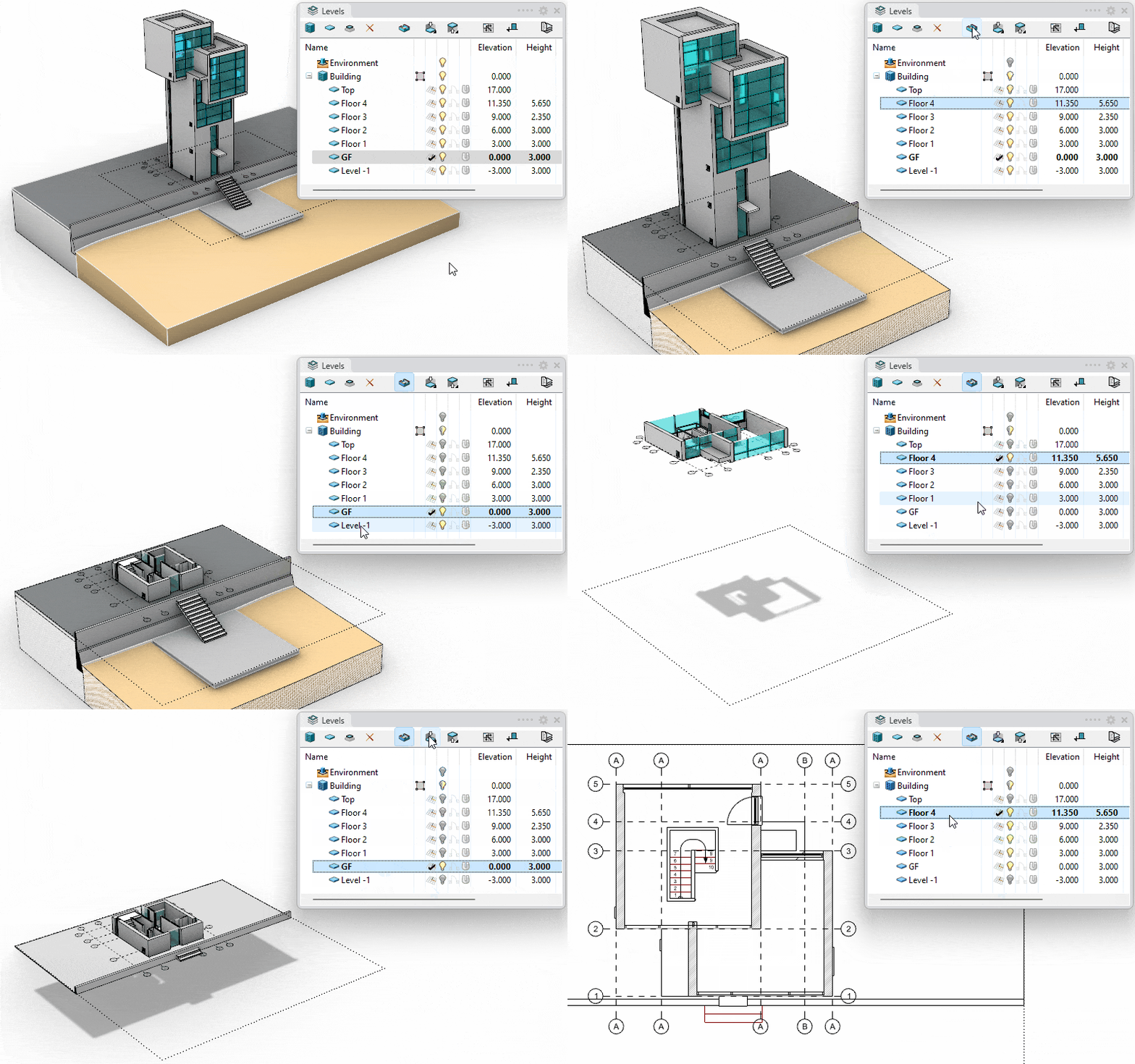
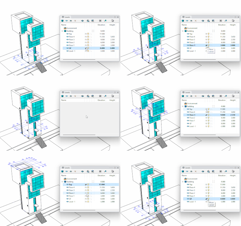
- Work with buildings and levels: The Level Manager panel allows to create and control new buildings and floors at different levels. From the Level Manager, you can have control of each level CPlane (working plane), display, and 2D representation, as well as its elevation and cutting plane values.
- Show and hide buildings and levels in 3D: Set up a boundary for your buildings so you can show, hide, or isolate them. The Level Manager enables horizontal clipping planes to show and hide levels individually.
- Easy navigation workflow: Just by double clicking on the level name, the model displays the selected level sectioned and the levels underneath.
- Plan view display: In the Top viewport, when the Cut Plane is On, VisualARQ objects are shown in their 2D graphic representation.
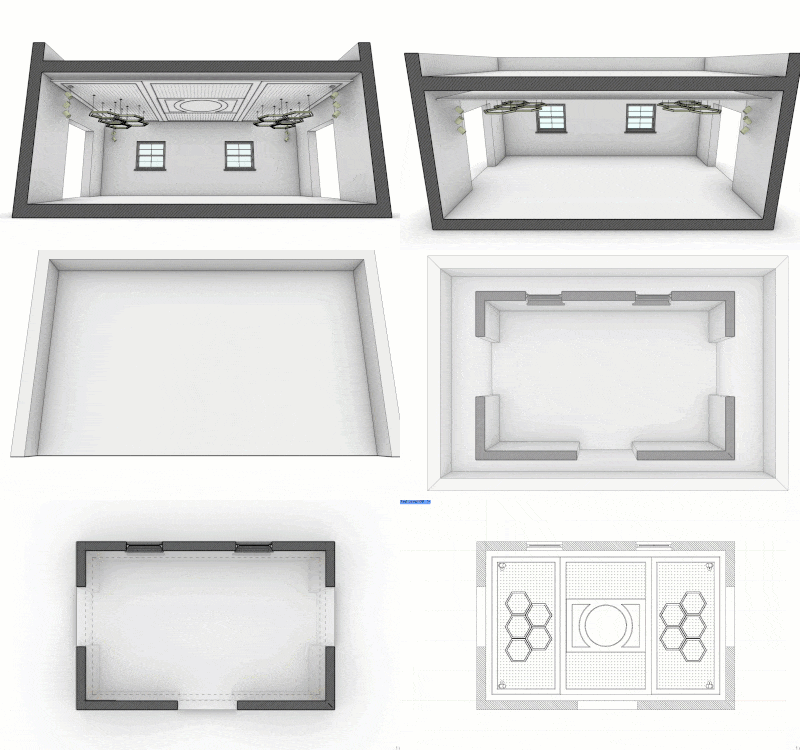
Reflected Ceiling Plan views New in VA3
Show the reflected parallel view of a specific level in any viewport.
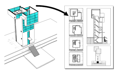
Align view to level and Set plan view to viewport
Set plan views and reflected ceiling plan views to viewports and layout details, ready to be printed.
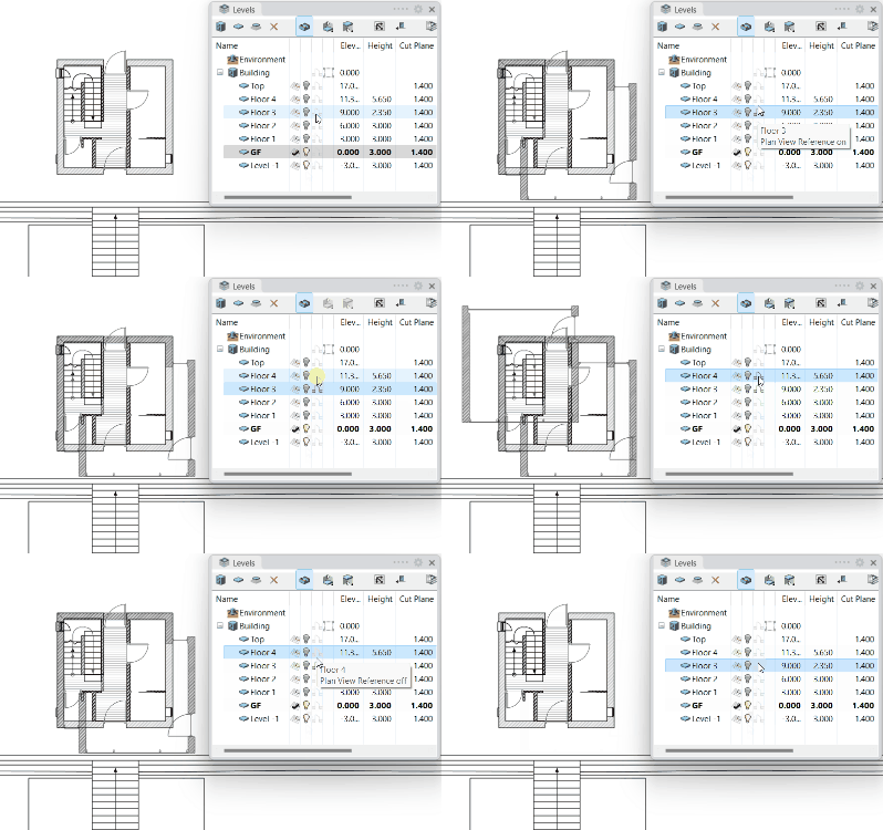
Reference plan views
Display the plan view representation of different levels projected on the current level.
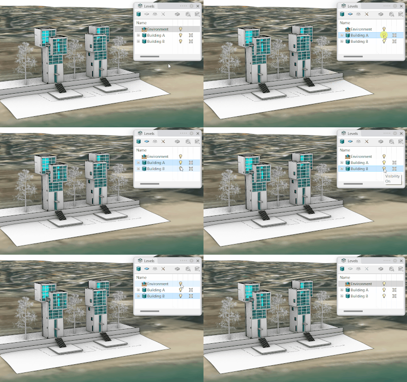
Environment New in VA3
Show or hide the geometry located in the area outside the building’s boundaries.
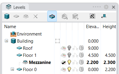
Sub-levels New in VA3
Option to add new levels as sub-levels between levels.
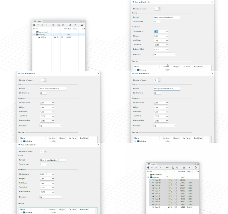
Create multiple levels New in VA3
Option to create multiple levels (or sub-levels) at once, with a specific pattern for names, or height between levels.
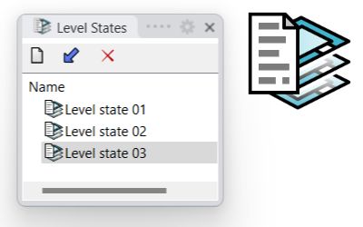
Level states New in VA3
Save level and building configurations to restart them at any time.
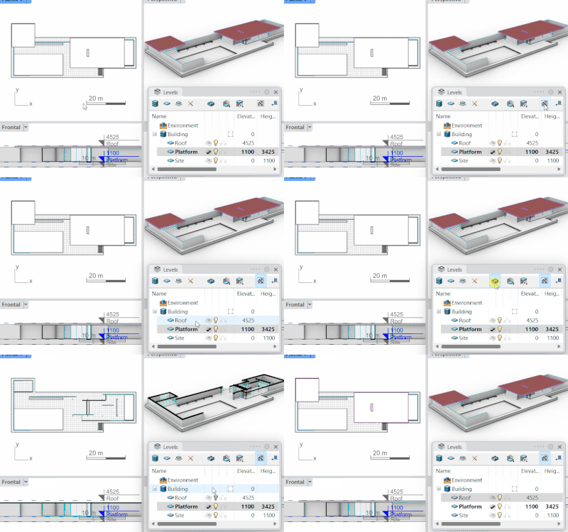
Synchronize Level states in viewports New in VA3
Show the buildings and levels visibility status in all viewports.
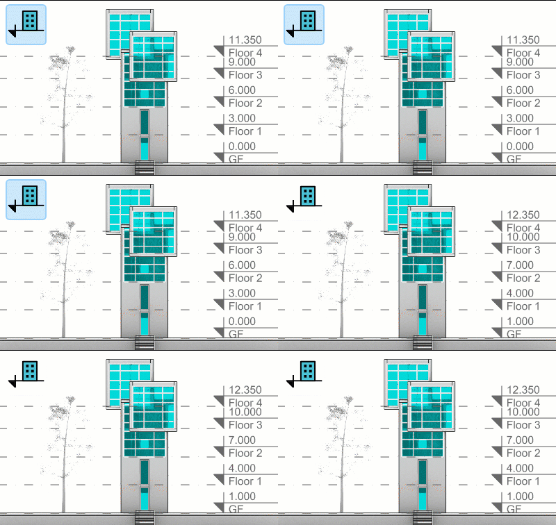
Toggle level’s elevation New in VA3
Level elevation is displayed as referenced lines in elevation viewports. This level’s reference can be shown in relation to the building’s elevation or to the Document’s Elevation.
The Section Manager
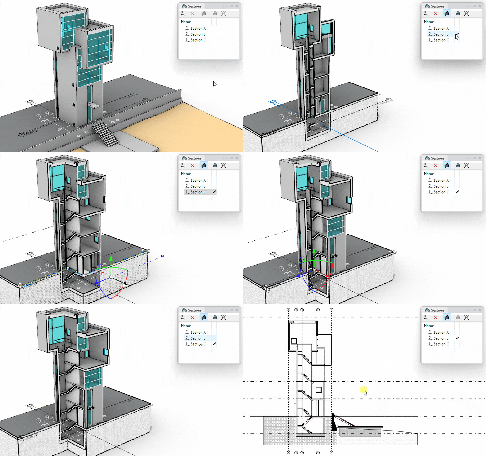
- Activate sections: See the list of section lines in the model and show the model in a real-time section activating any of them. The sectioned geometry will show the section attributes defined by the Section styles.
- Easy workflow: Just double-clicking on a section name in the list to show the model in a section in a specific viewport.
- Jogged sections: create section lines with different control points that can be added or removed.
- Align view to section and Set section view to viewport: With just one click you can align the view to a section line position, activate the selected section or leave section views ready for printing.
Guides
New in VA3 Guidelines play a crucial role in the architectural design process by promoting accuracy, consistency, organization, collaboration, efficiency, flexibility, and clarity. They enhance the quality of architectural drawings and contribute to successfully realizing a building project.
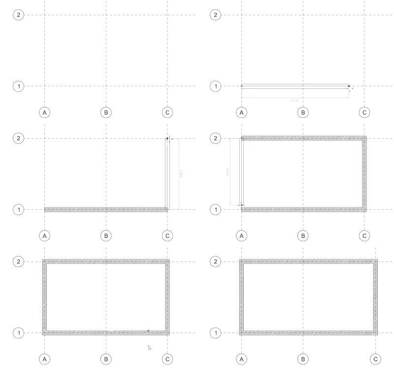
Accuracy and consistency in design
Guidelines help you maintain accuracy and precision in your project and therefore promote consistency throughout the design process. They act as reference points and aid in aligning different elements of the design.
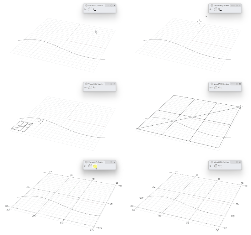
Easy of use
Insert guides individually, from curves, or arranged in a grid, with automatic naming control. Control their visibility by viewport, or by CPlane.
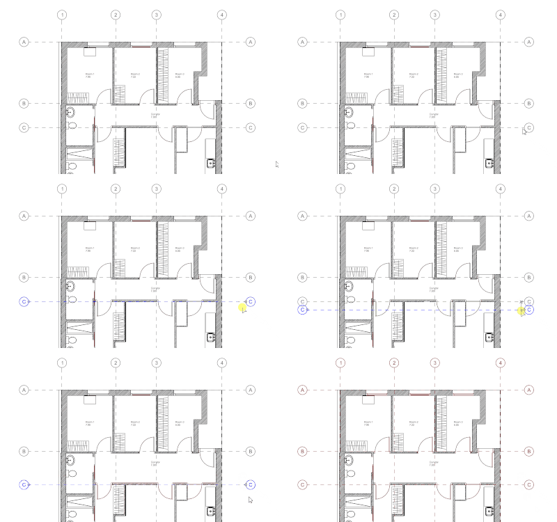
Objects link to guides
VisualARQ objects and Rhino geometry get linked to guides, so they move when guides change position. The guide styles can determine which object types are linked to guides.
Dynamic display in different viewports
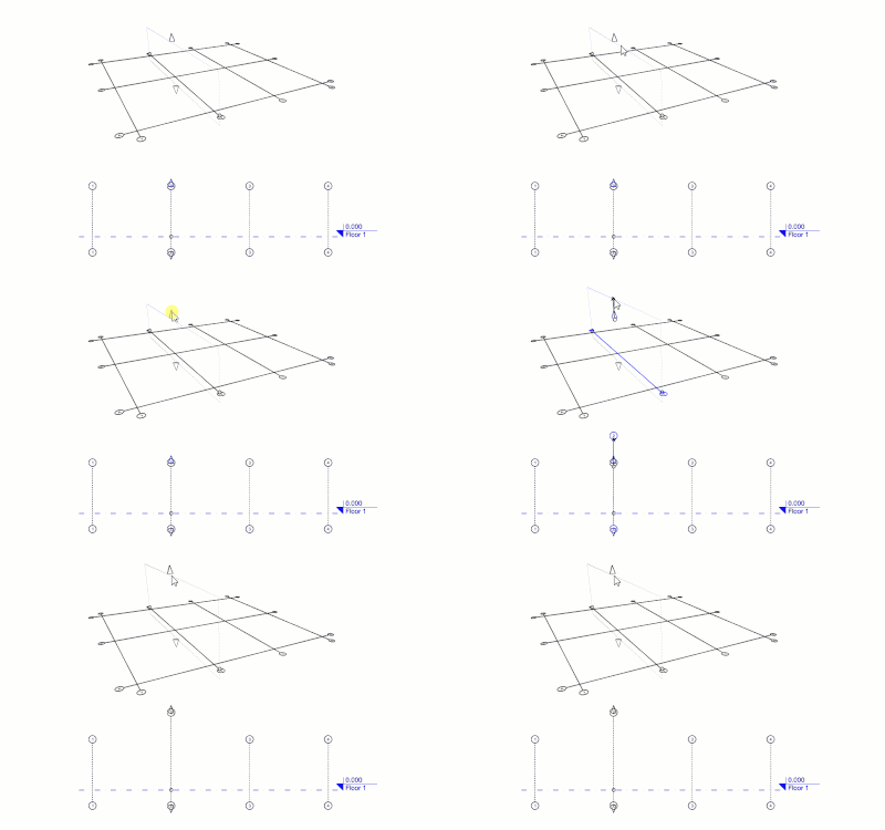
Guides are displayed on the construction plane of the current floor in the Top and Perspective views and as vertical reference lines in elevation views. They can also be displayed on all levels simultaneously.
Range and Control points
Guides have control points and top and bottom extension arrows to change their vertical range and label position.
Layers
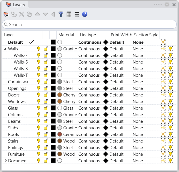
- Layer panel: Control easily the layer and sub-layer Properties: On/off, Lock/Unlock, Color, Material, Linetype, Print Color, Print Width. You can create layers that are subordinated to other layers.
- Layer properties in Page Layouts: They can be defined by Page Layout and Detail view.
- VisualARQ layers: When VisualARQ objects are created they are automatically located in a specific layer defined by object type. That makes it easy to hide, show, select, and define common attributes by object type.
- Layer State Manager: Saves the current state of layers to a file or restores the state of layers from a saved file.
The Profile Manager
New in VA3 The Profile Manager
The profile Manager lets you create, extract, delete, or edit custom profiles that can be used on different VisualARQ object types and style components. Changes on these profiles will apply to the objects using them.
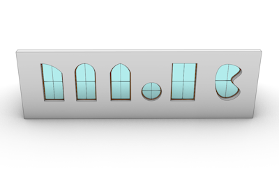
Profiles for openings
Some standard profiles (Rectangular, Circular, 90º Arch, Gothic, Romanic…) are available for openings, but you can create new custom ones from curves of any shape.
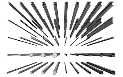
Profiles for structural elements
Rectangular, Circular, hollow, I, H, L profiles, and the custom ones you want to create.
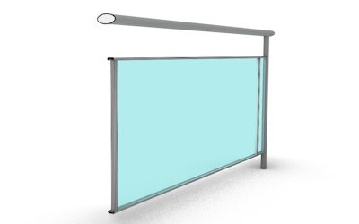
Profiles for style components
Many of the object style components, such as railing posts, or curtain wall mullions, accept any of the profiles available, including the custom ones.
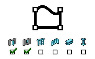
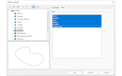
New in VA3 Custom profiles by object type
Select which object types are available for each custom profile in the Profile Manager.
Custom Templates
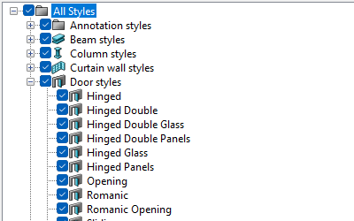
Object styles library
VisualARQ templates include the full library of parametric object styles (in metric and imperial unit systems) which already have some attributes assigned. They also come with a building and a level already created in the Level Manager.
Fully customizable templates
These are some of the parameters that the user can adjust for a custom template, so they are ready in new documents: Object styles, Level Manager settings, Layer settings, Title blocks, Page Layouts, Drafting attributes for documentation drawings, Materials, Graphics, or IFC schemes.
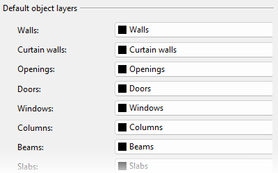
Object Layer Configuration
VisualARQ objects are created by default to some predefined layers which help the management and visualization of objects by type. This configuration is fully customizable.
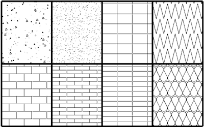
New hatch patterns
In addition to the hatch patterns available in Rhino, VisualARQ templates come with some typical and useful hatches widely used in architectural drawings: concrete, gravel, sand, bricks, tiles, insulation….
Edit Tools
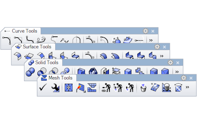
Edit tools for any geometry
Fillet, chamfer, offset, extend, trim, split, join, boolean union, boolean difference, and more. All these commands adapt to each object type: Curves, Surfaces, Solids, Meshes, and VisualARQ objects.
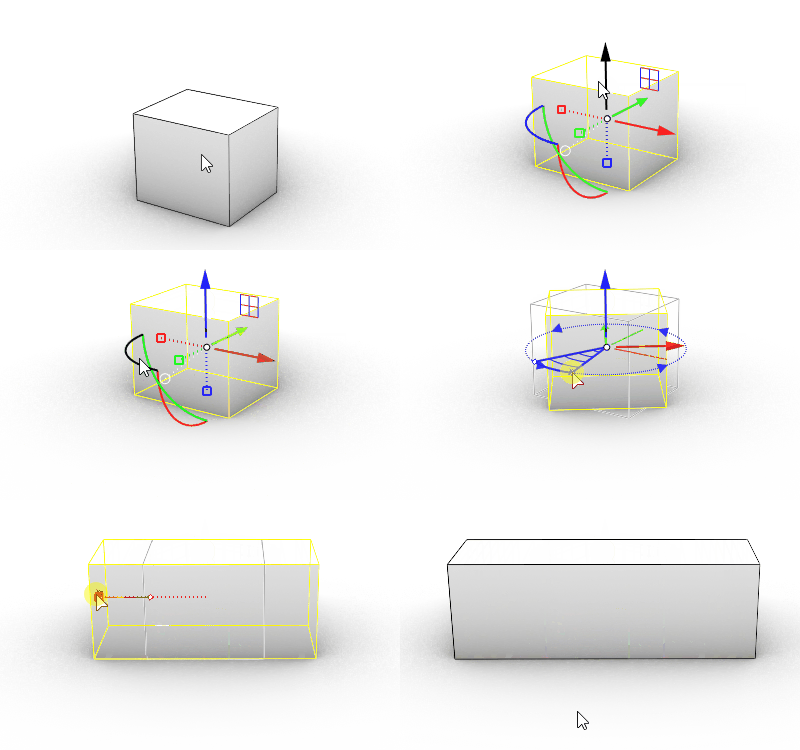
The Gumball
The Gumball is a customizable interface widget that allows interactive editing of objects and sub-objects. The Gumball helps you move, rotate, and scale the geometry easily.
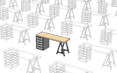
Blocks
Working with blocks lets you create parts libraries, and update all instances by modifying a block definition or keeping a smaller model size by using block instances instead of copying identical geometry. Some VisualARQ objects can be created from blocks.
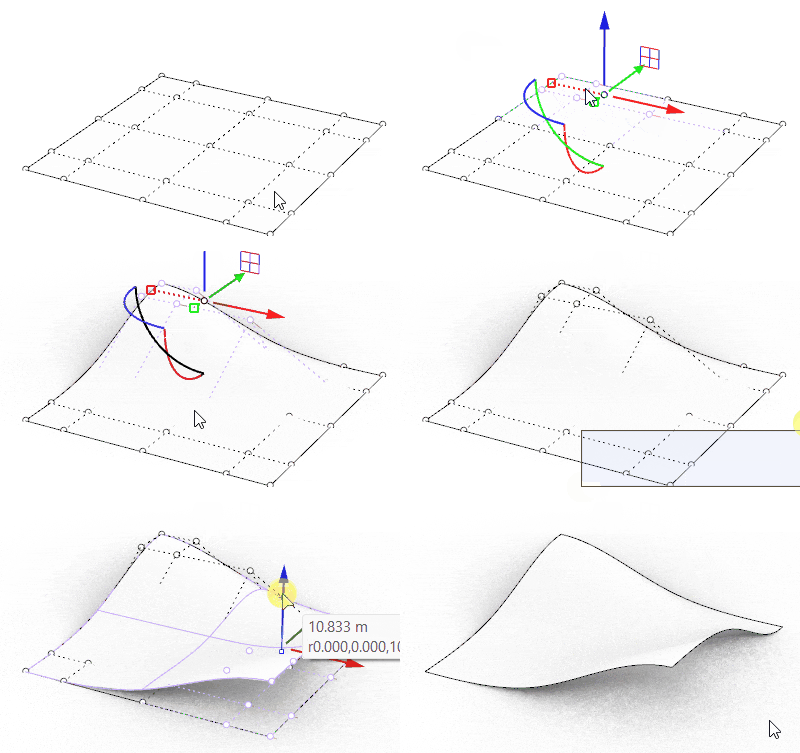
Control points
Curves, surfaces, extrusions, and meshes can be modified through control points. And VisualARQ objects too. These control points are the same as the curves they were created from.
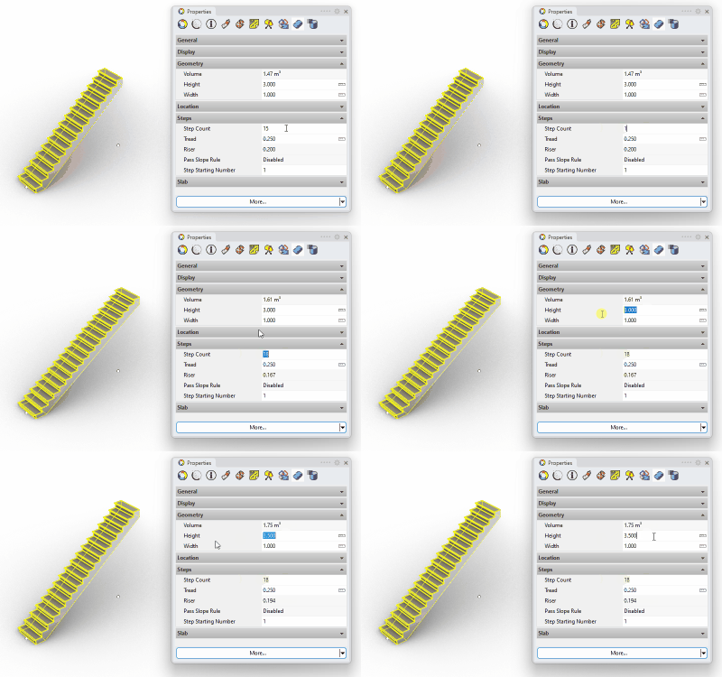
Intuitive properties dialogs
The object properties panel or the object styles manager (for VisualARQ objects) provide an intuitive interface to easily edit object parameters and attributes.
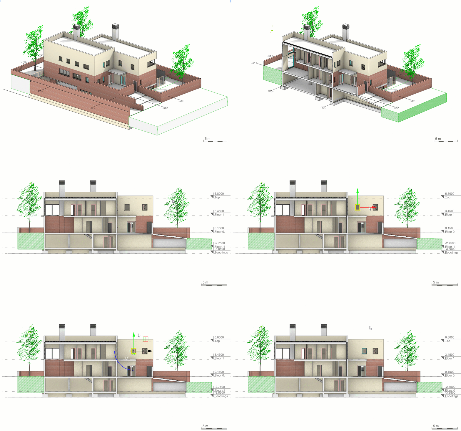
Work from sectioned models:
Turn sections and Levels cut planes on, as well as Rhino clipping planes, and work from the inside of the building. It makes it easier to select and edit objects.
3D Model and Layout Views
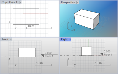
Model viewport
Displays the Rhino working environment including object display, viewport title, background, construction plane grid, and world axis icon. Viewports can be resized, added, deleted, or expanded.
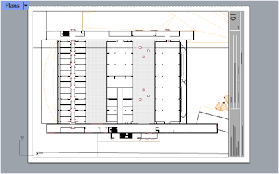
Layout viewport
Represents the sheet of paper that will be sent to a printer or a file such as PDF. Layouts can include various views (“Details”) of the model and annotations like title blocks and notes. Layer visibility and attributes can be set up by each Detail viewport individually.
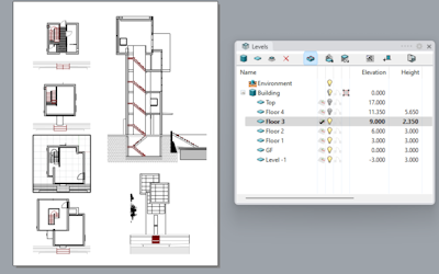
Print plan and section views
VisualARQ levels and sections can be displayed individually per Detail viewport and printed to vector output using the Hidden display mode.
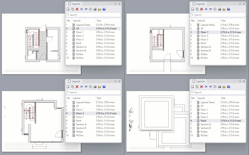
Layouts panel
This panel lets you navigate easily from multiple layout sheets and simplifies many of the tasks associated with layout management.
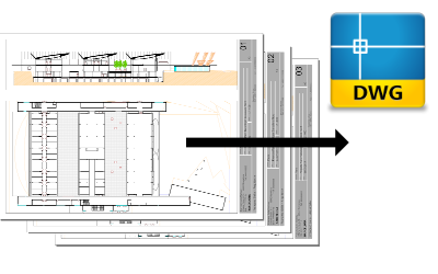
Export Layouts to DWG New in VA3
A specific VisualARQ command lets you export one or multiple layouts to DWG.


