Documentation Tools
Tables and Parameters
All VisualARQ objects have native information (such as the Name, Style, Area, Volume, Height, etc, etc… ) that can be listed in tables. But new parameters can be created for any kind of object and listed in tables.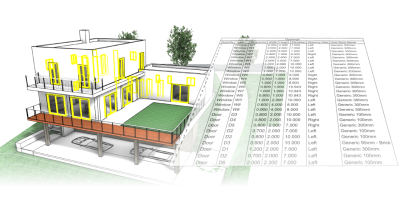
- New custom parameters: (Video) Create new parameters by Document, by VisualARQ object style or by object individually. Custom parameters are typed (numbers, texts, booleans…) and can be shown in tags.
- Feed geometry with information: The values of new parameters can be assigned to any piece of geometry, besides VisualARQ objects: points, curves, surfaces, polysurfaces, blocks, meshes.
- Export custom parameters to IFC: Custom parameters and their values assigned to geometry are stored in IFC files.
- List the object information in tables: (video) Create new table styles to quantify objects, define the object types to list, and define the table property fields (area, length, volume, custom parameters, etc…). Group objects and show the sum of objects with common parameters.
- Dynamic tables: Tables are linked to the model: when the model is edited, the information shown inside the table can be updated using the update command.
- Export tables: Once the tables are created they can be exported to Excel and .csv format.
Spaces
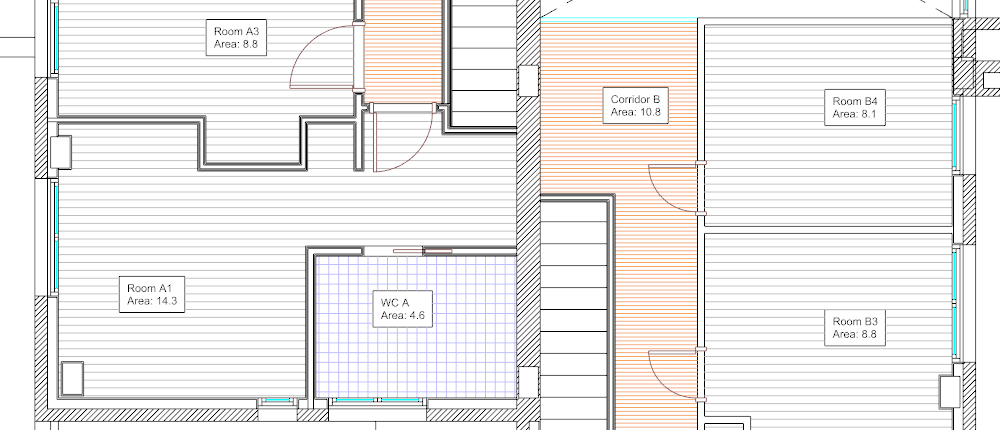
- Create Spaces: (Video) Insert spaces from inner points (of a closed boundary made of walls and/or columns), curves or surfaces, and see their information (name, area, perimeter, etc) in labels. Spaces are displayed in 2D with a label and a hatch pattern and in 3D as a volume with dashed lines edges.
- Set spatial elements: Convert any geometry element (curves, polysurfaces, VisualARQ objects) into an entity that is taken into account when calculating spaces.
Tags and annotations
- Tags: (Video) The tag command inserts labels at the bottom of each object and displays a referenced text. Tags can show dynamic information of VisualARQ objects, according to the objects properties. A list of tag shapes (rectangular, circular, hexagonal, etc…) is provided but new shapes from blocks can be used too.
- Annotations: (Video) The annotation object can be a 2D symbol, a text, a dynamic 2D geometry or a combination of 2D elements. They are created from blocks, or from Grasshopper definitions, providing no limits of parametric designs.
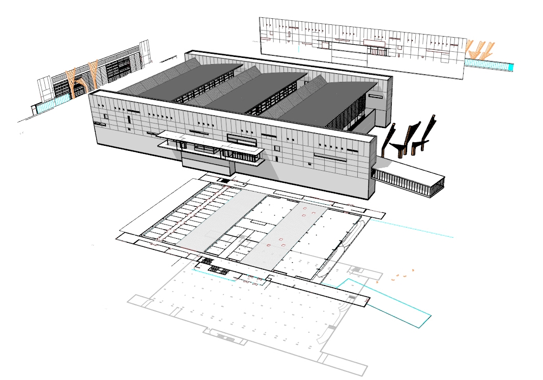
Hidden-line vector output 2D drawings
VisualARQ provide tools to print the model in 2D from 3D views, horizontal and vertical sections. (Video)
These drawings can be generated in real-time by printing the 3D model seen in plan, section or perspective views from the model space or Page Layouts. Just use the Hidden display mode and print these drawings in real-time vector output!
- Plan views: Set the Level to display from the Level Manager and print plan views.
- Section views: Select a section line in the Section Manager and Set section view to viewport to print sections and elevations.
- Perspective views: Put the 3D view in Hidden display mode and print it in vector output.
Make 2D sections, elevations and plan views
VisualARQ provide tools to generate dynamic 2D drawings from horizontal and vertical sections.
The 2D drawings generated represent the 3D objects projected on a plane so they have the same display and printing attributes. These drawings are linked to 3D model so they can be updated at any change.
- 2D Plan views: Insert 2D plan view drawings from a specific Level. The 2D resulting geometry shows the projection of the visible 3D objects located inside the plan view area and a view depth (that can both be edited).
- 2D Section views: Insert 2D sections or elevations from a selected section line. The 2D resulting geometry shows the projection of the visible 3D objects located inside the section area, as well as a section reference text.
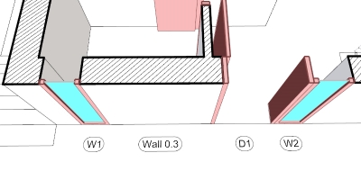
- Opening elevations: (Video) Create 2D drawings for all the selected openings (doors and windows) in a model. They are displayed in the Plan view with their main dimensions and with a reference that identifies their location in the model.
- Objects Layer and 2D attributes: The 2D geometry of section and plan views keeps the layers, line-weights, colors and other attributes of the 3D geometry it represents.
- Make 2D: The Make 2D tool projects geometry to the construction plane to make a 2-D drawing. Unlike VisualARQ Section and Plan Views, Make 2D drawings don’t update after changes on the 3D model.
- Export to .dwg: These 2D drawings can be exported to .dwg or exploded in order to work with the resulting lines and hatches.
Section attributes
 The Section attributes determine the attributes (features) of Rhino and VisualARQ objects in section for display and print purposes. These section attributes also apply to the sectioned geometry when activating cut planes and sections. They show up as well in Plan and Section Views. (Video)
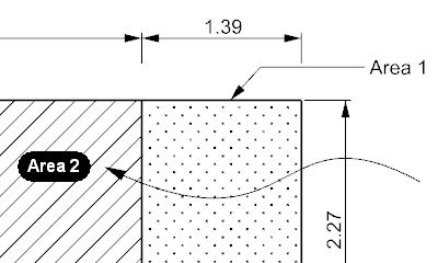
- Section attributes: Fill Color, Linetype, Line Print Width and Line Print Color. Pattern Type, Scale, Angle and Color.
- Assign them to any kind of geometry: Section attributes can be assigned to any geometry in Rhino (surfaces, solids or meshes) from the Section attributes icon, in the Rhino Properties panel. VisualARQ objects can also get the section attributes assigned by Style, from each object styles dialog.
- Clipping status: A clipping status can be disabled by object so it’s not sectioned by an active VisualARQ section, a Level cut plane or a Rhino Clipping plane.
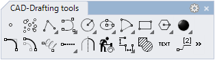
Plenty of CAD-Drafting tools
Rhino and VisualARQ provide all CAD and Drafting tools required to produce 2D architectural drawings, construction details and any kind of annotations.- Work with 2D geometry: Draw lines, polylines, rectangles, polygons, circles, elipses, control point curves, etc… Edit them with different commands: fillet, chamfer, offset, extend, trim, split, join, rebuild… Curves can be also edited through control points.
- Dimensions: Several commands are available to create dimensions that are defined by styles which manage font, number format, sizes, arrow style, alignment settings for the current model.
- Hatches: Hatch patterns are created from bounding curves.
- Text: The Text command creates two-dimensional annotation text that can be quickly edited through an edit box.
- Leaders, Dots, Notes: Other annotations are available for complementing the documentation of the project.
- Linetypes: Annotation linetypes manage the linetype patterns for the current model. They are managed by styles that define the scale, units or pattern and can be imported into new documents.